The structural stages are laser cut from acrylic and wood. The components positioned placed for a better center of mass.
Plagued with electrical failures, leading to less time for control algorithm optimization, the robot worked somewhat successfully. With more time and more money (the project was funded on our own) the controls could be tuned with better sensors.
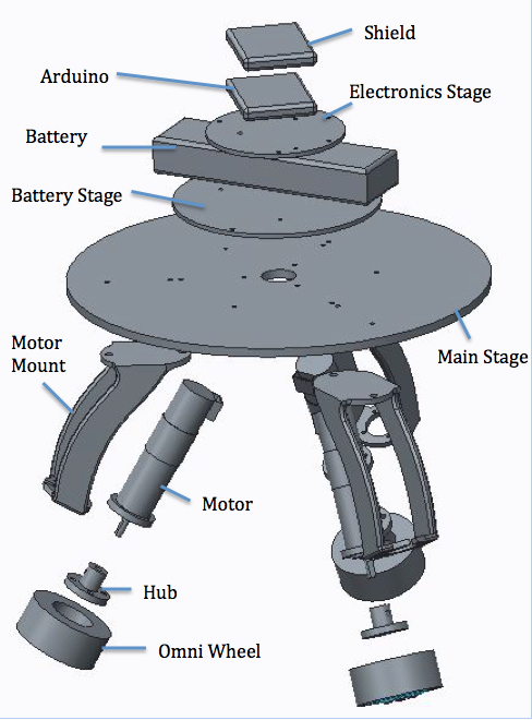
Exploded view of assembly.
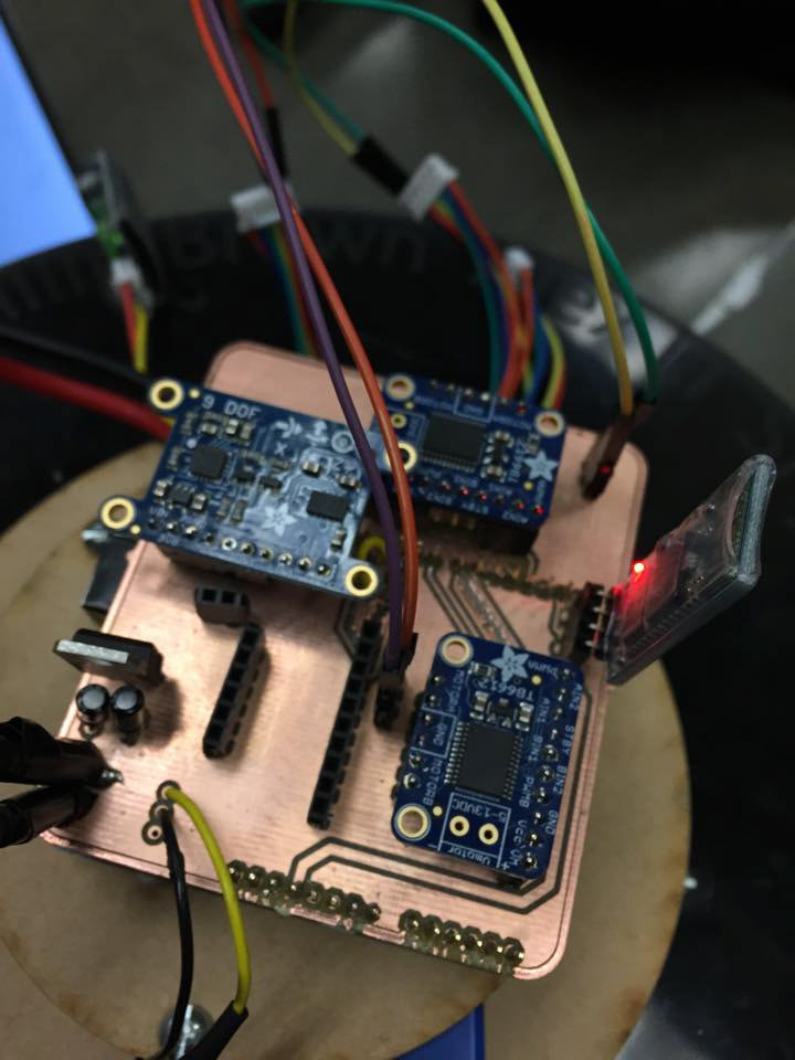
Finished PCB out of the mill and assembled!
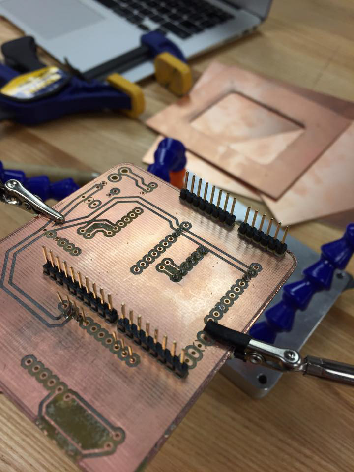
Milled PCB with header pins soldered in.
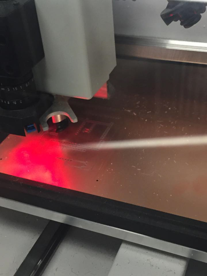
PCB in the milling machine.
Setting up the milling operation.
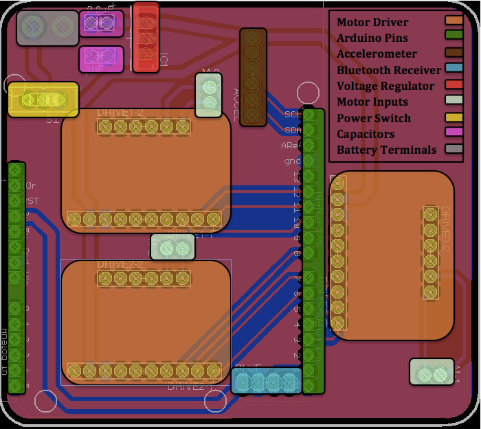
A colored coded diagram of the components attached to PCB.
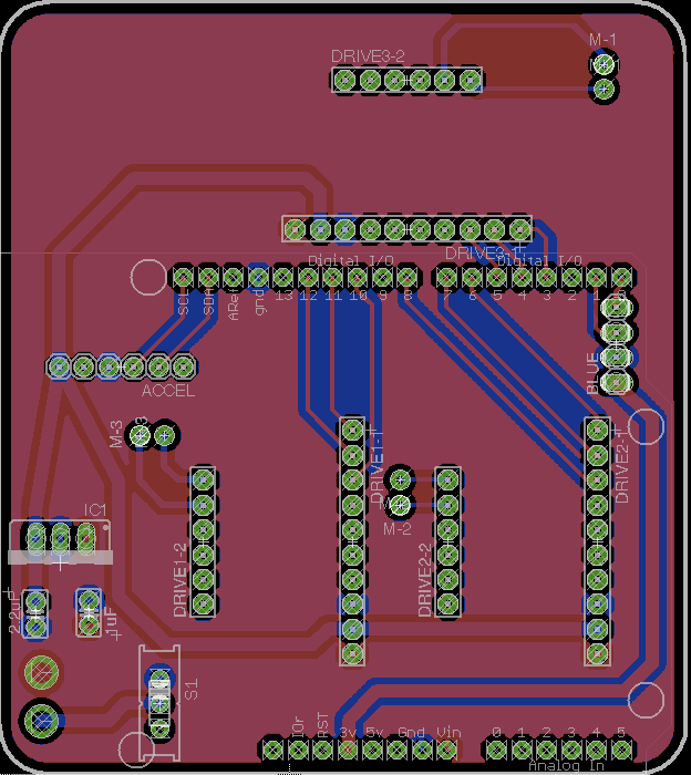
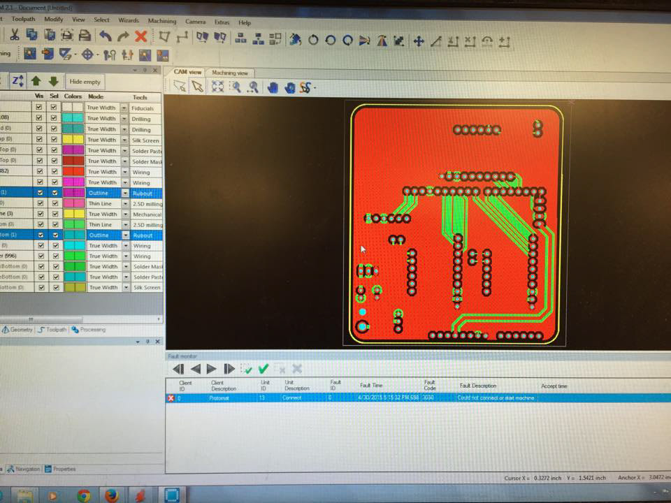
I learned EagleCAD to layout the PCB for it to be milled.
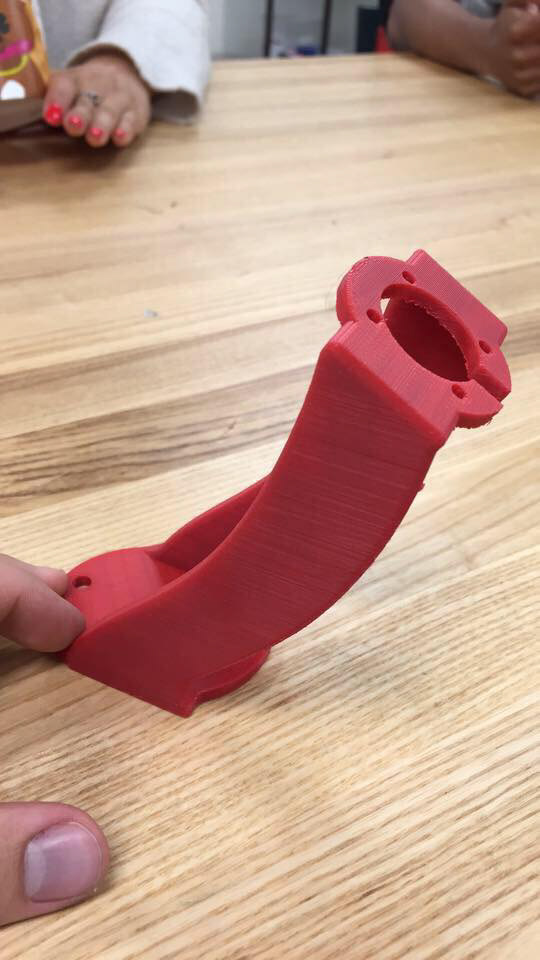
3D printed motor mount.
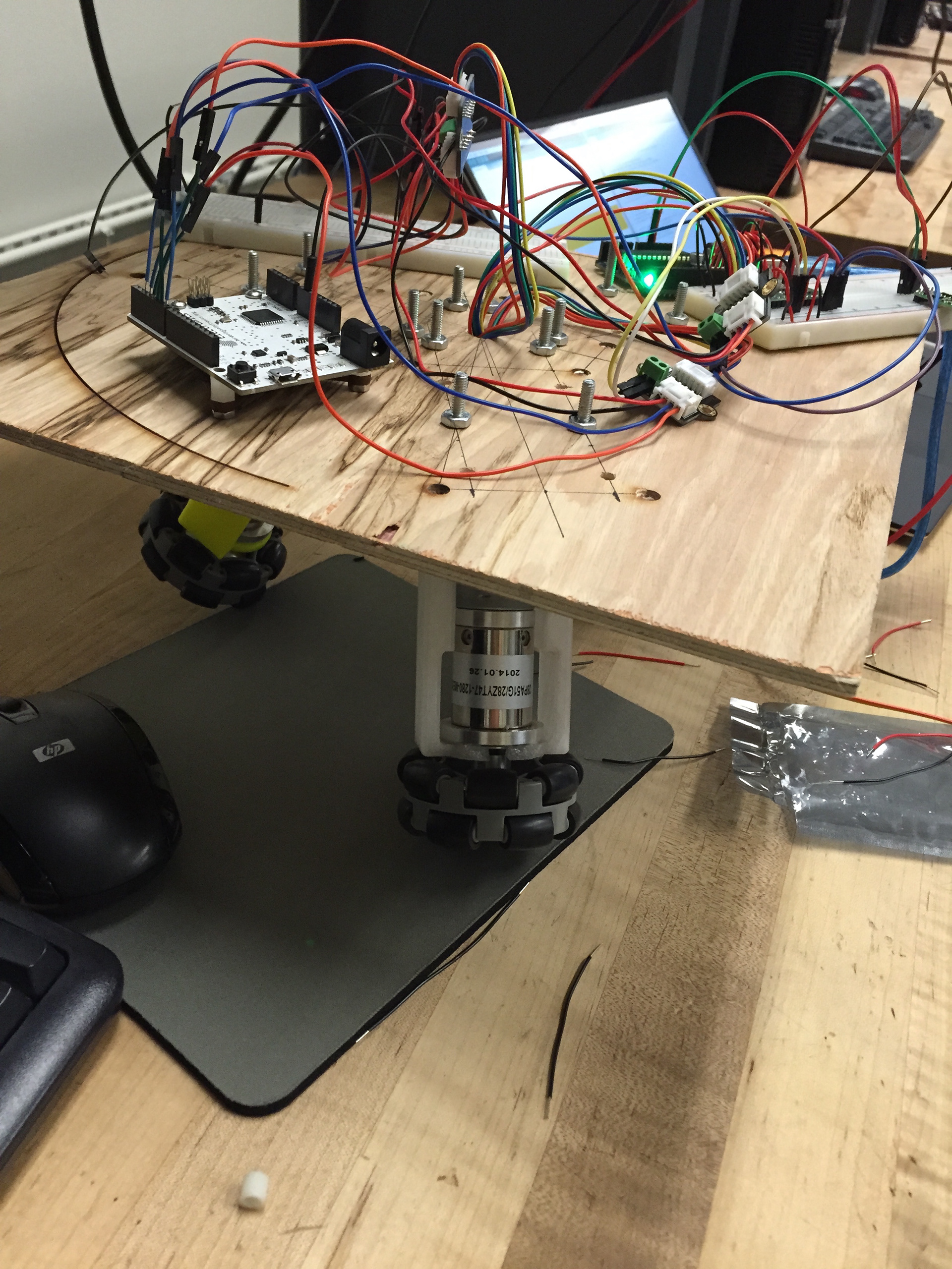
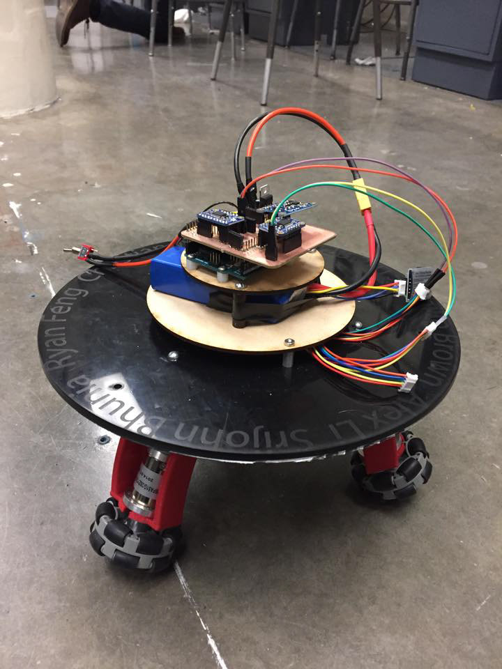
First iteration before PCB integration.
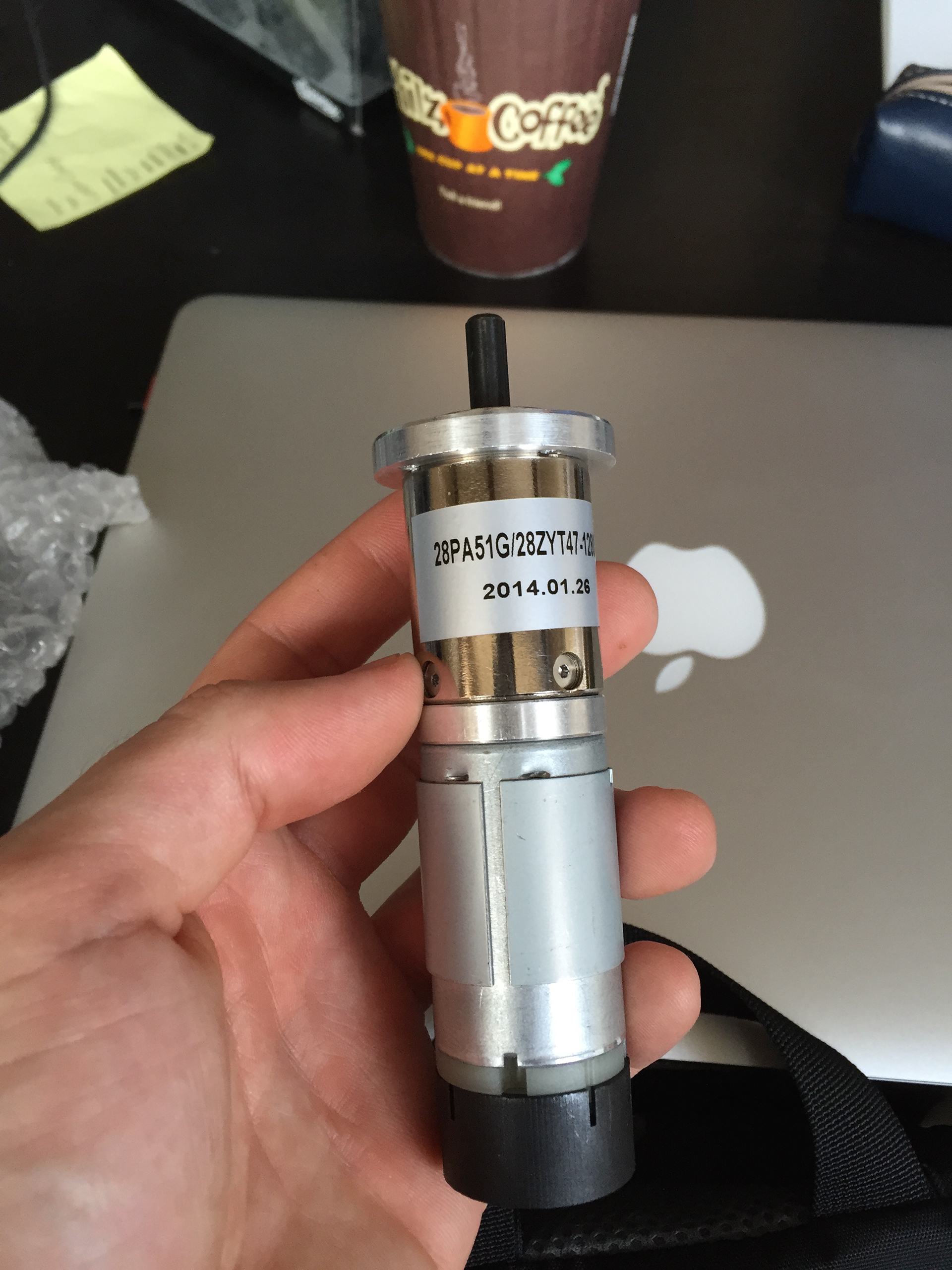
12V DC Motor 146 RPM with encoder. It has a 51:1 gear ratio and a whopping 10 kg-cm of torque at 12V.
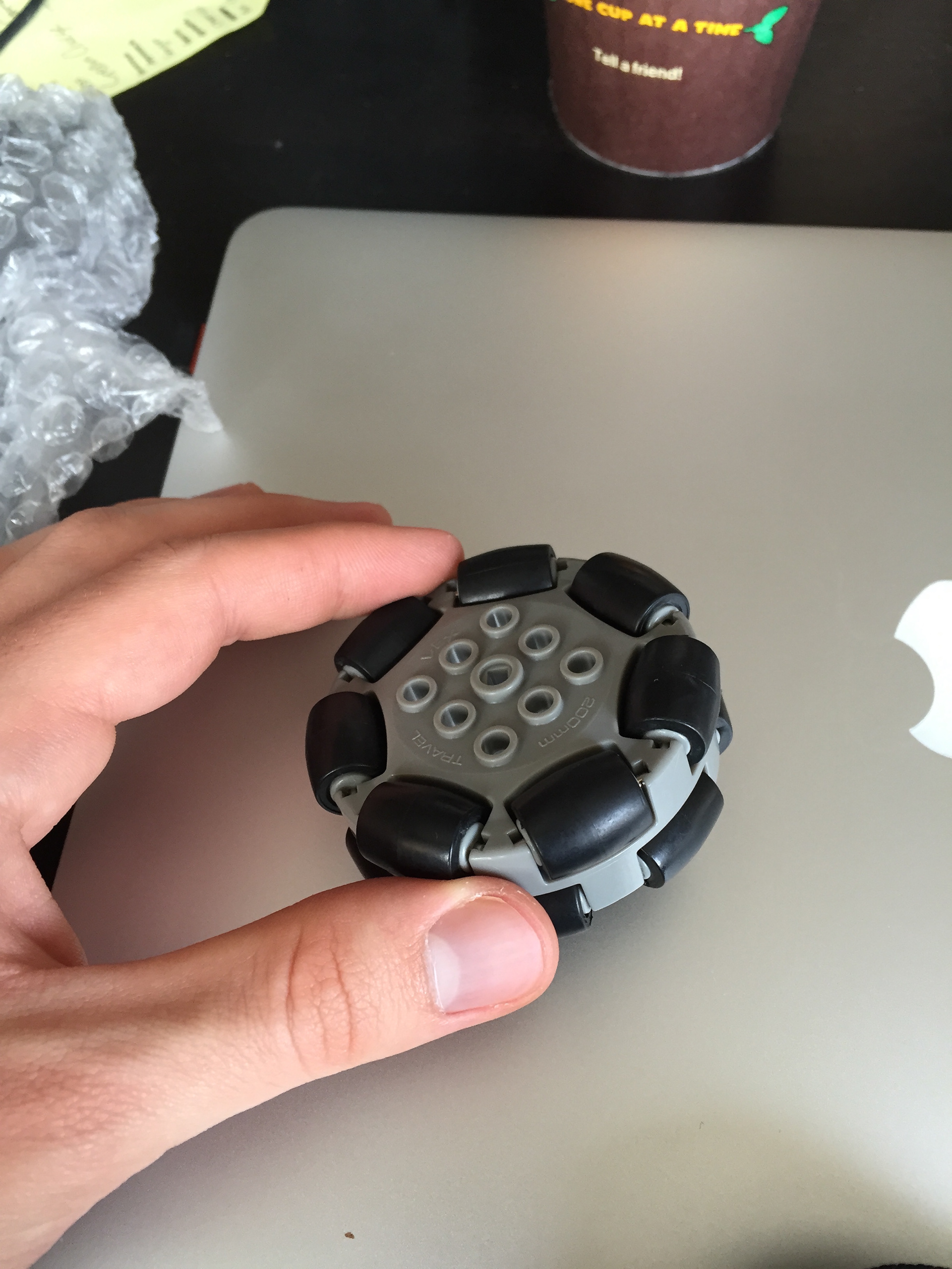
Omni-directional wheels allow the wheels to spin on the ball, but also not scrub as the ball rolls in various directions.